Cisco Band Select configuration

Cisco Band Select configuration

All information here and more can be found at Cisco.com, this was just the information I needed to have for a basic understanding of what it does and how to configure it.

Works by delaying/suppressing the first few 802.11b/g probe frames so that client will accept the 802.11a probes because it will appear to have a quicker response time.

  • Band select is configurable only when the radio policy is set to ‘All’.
  • Band select on supported on all types Aps.
  • This feature only works when a client first associates to AP.
  • This feature will not start when the AP notices a high client count or high channel utilization.
  • This feature only goes in one direction ‘2.4GHz >5GHz’ not the other way. Means it will not load balance clients on AP.

Do not use Band select on Voice or other real-time applications, or use with caution and ensure proper testing is conducted, as it can cause roaming delays or dropped calls

 Network configuration

  • Disable by default

Global Band select features

  • The Probe cycle count is the number probe beacons/frames to ignore/delay before a client will associated at 2.4GHz
  • The cycle period is how much time in milliseconds needs to pass for next associating attempt to be considered a unique attempt.
  • Age out Suppression: When the clients will be declared as “new” and may have their probe frames delayed/ignored again.
  • Age Out Dual Band: The AP will not respond to a 2.4GHz probe until a (dual band) client is no longer marked as dual-band (default is 60 seconds). This is to prevent clients associated on 5GHz radio from switching bac to 2.4GHz radio
  • Acceptable client RSSI is how well a 2.4GHz client needs to be heard before trying to push them to the 5GHz band
  • Features can be controlled per-WLAN under the “Advanced” tab

From gui:

1.PNG

2.PNG

3.PNG

4.PNG

5.PNG

6.PNG


Cisco 3802i CAPWAP AP Conversion to MOBILITY EXPRESS ACCESS POINT and configuration.

Notes*

Require a minimum of 802.3at POE to power 3802 series AP’s. (they will turn on but radios will not work if not  receiving 25.5W)

Require network connectivity with a DHCP server configured, as the Lightweight access point will send out DHCP request for an IP address (saves doing it manually)  can use Tftpd64 as DHCP server and TFTP server.

When trying to convert to Mobility Express Image the Access point must not join and existing WLC in your network

Download Mobility Express image from www.cisco.com. You will need a Cisco account to download this image.

1.PNG

Suggest downloading the lightweight image  as well in case you want restore the AP

2.PNG

Connect Console and Ethernet cables into their correct interface ports, Ethernet will also be used to power through the use of a Power injector

3.PNG

Plug Ethernet cable from network switch into data port of POE power injector unit and apply power to POE injector

4.PNG


Below log messages are showing that the Lightweight Access point (LAP) is trying to look for a WLC via DHCP request broadcast packet.

5.PNG

Log on to LAP with default username and password of Cisco.

6.PNG

Check that the LAP has been assigned a IP address from the DHCP server on your network. Identify that an IP address has been assigned to the LAP

7.PNG

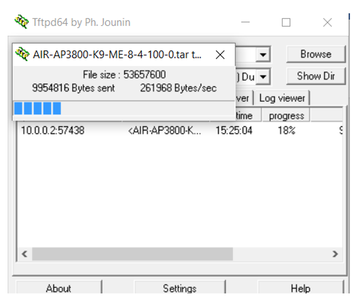
Setup your TFTP server, (for this I will using Tftpd64) and browse to the folder that contains the Mobility Express image.

8.PNG

In the Command line of the LAP enter the following to download and change the configuration to Mobility Express.

AP#ap-type mobility-express tftp://<TFTP Server IP>/<path to tar>/file

Example:

AP#ap-type mobility-express tftp://10.18.22.34/AIR-AP3800-K9-ME-8.4.100.0.tar


9.PNG

When entered correctly the transfer will start

10.PNG

Once image has completed download the file will write to flash and LAP will reboot

enter “yes” to terminate the auto install.

Enter your required configuration items in the config wizard.

Below is a step by step of the WLC wizard configuration process.

11.PNG


12.PNG

13.PNG

14.PNG

15.PNG

16.PNG

17.PNG

18.PNG

Do a ping -t to show you when the AP comes online with the management IP address you assigned.

20.PNG

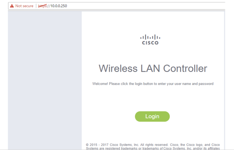
open HTTPS://IP address of WLC

21.PNG

23.PNG

24.PNG


and there you go.