Featured

My DIY Wireless Lab

I love getting to work and testing things in my home lab, so come my last holiday time, I decided to change up my home office and lab setup as it annoyed me to no end. It work but I was always looking for ways to make it better.

(At the end of the blog I will have listed the equipment used)

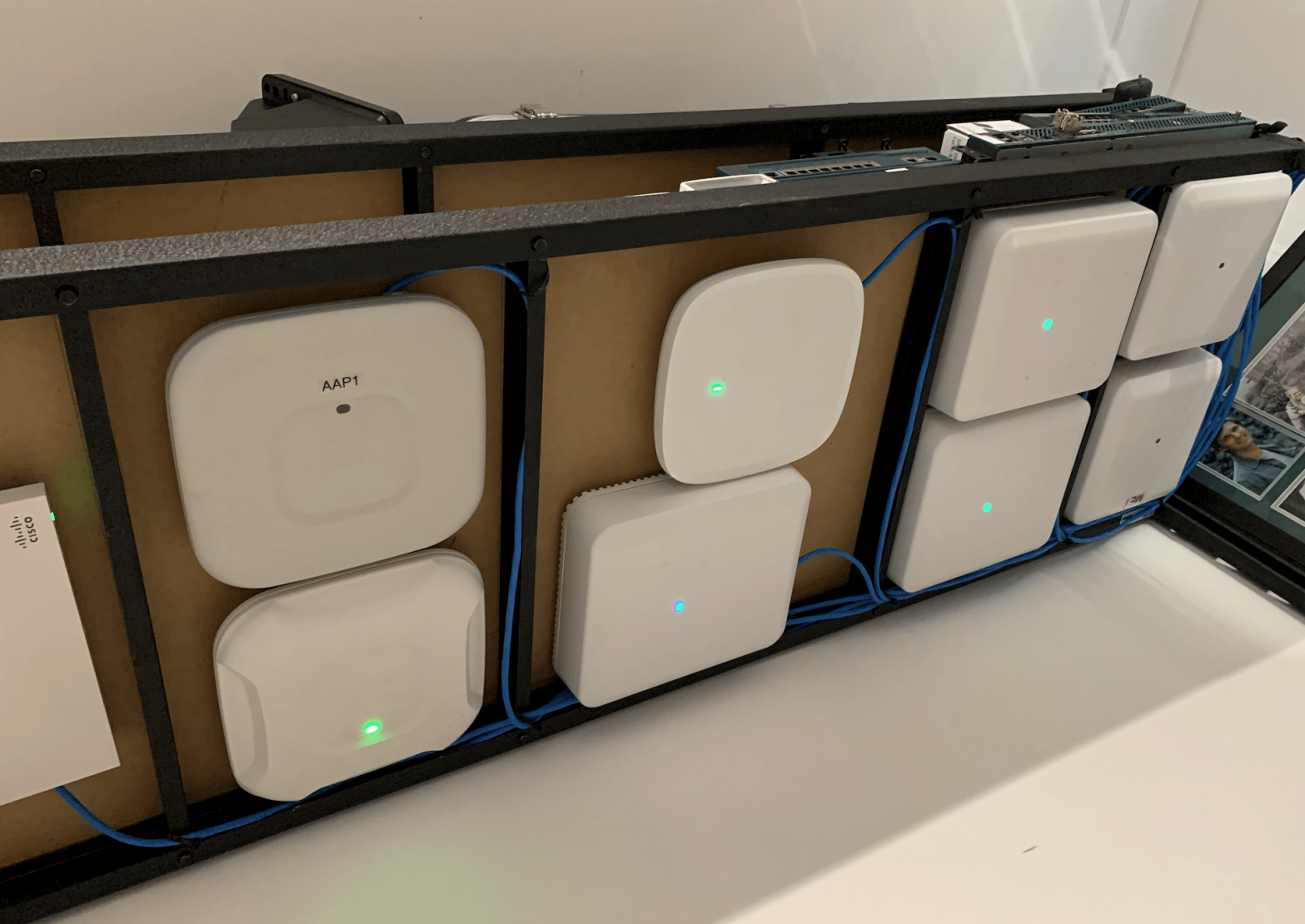
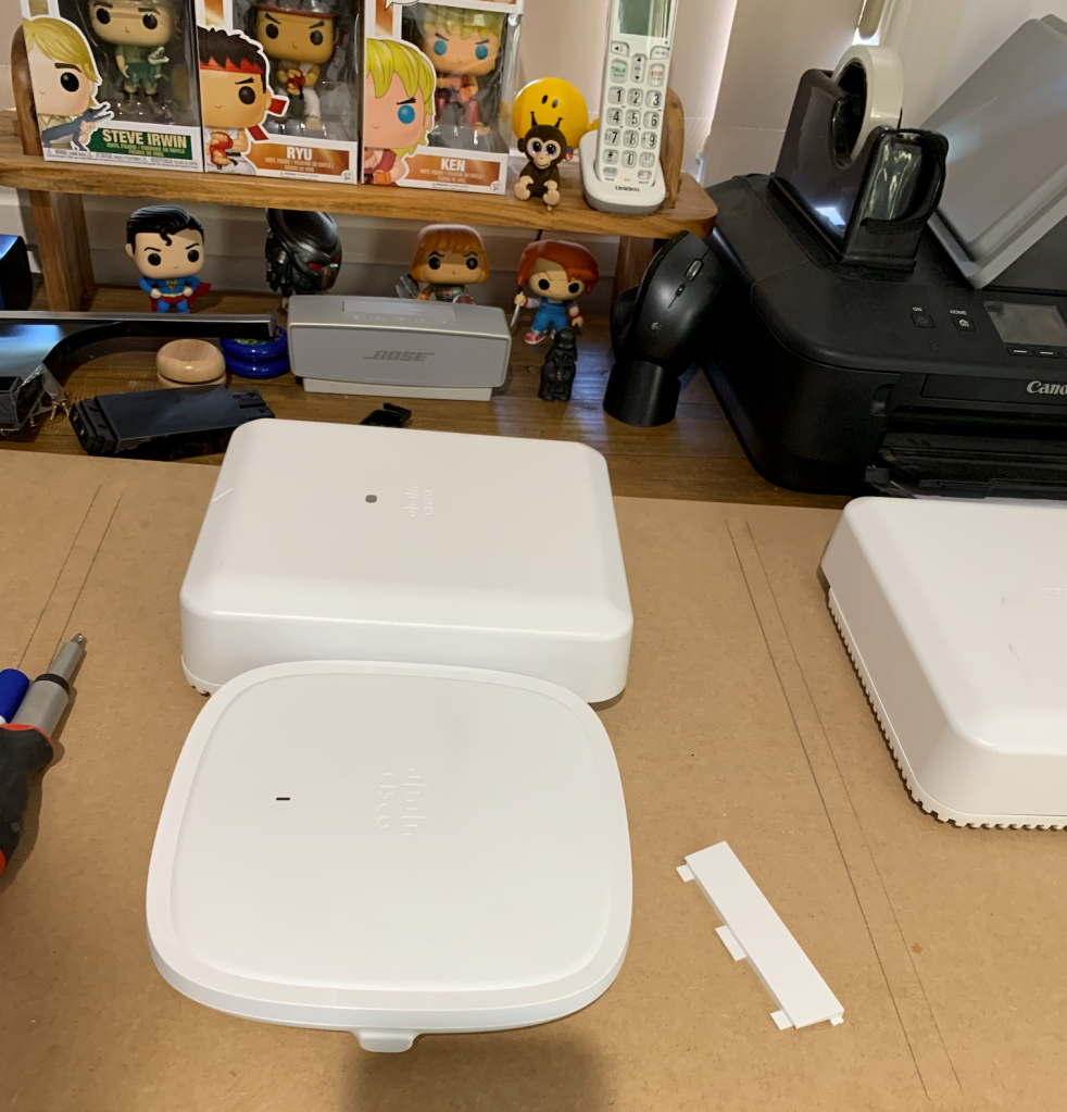
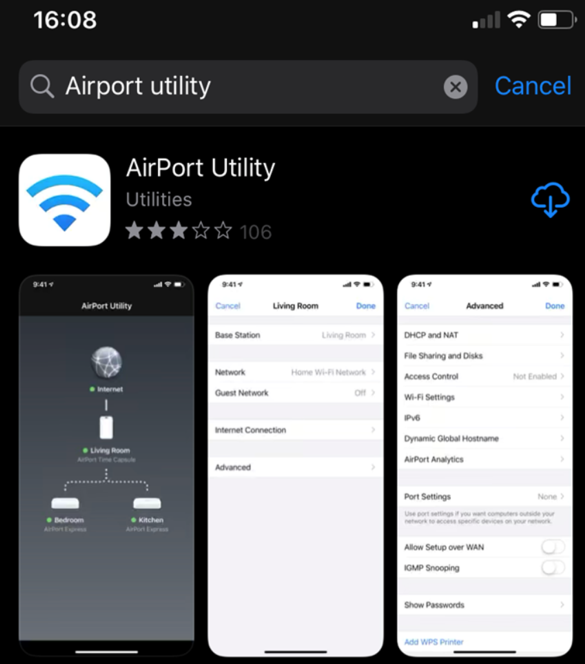
The 3 photos are of what my office use to look like, I also live on 2 acres so I have AP’s (1562e) mounted throughout my property to test different scenarios.

old office lab setup
fgfdgffgfg
Office table
Communication rack , I was pulling it a part at the time of the photo

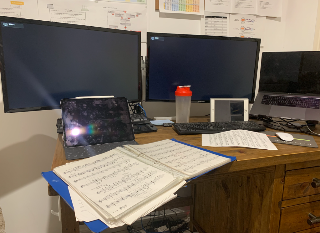
The space I called my office was really our family TV room and my office was stuck in the back, not ideal .

So after many discussions with my wife, I got my own space , I was able to change the spare bedroom into my office.

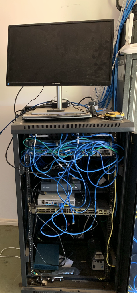
At first I just relocated everything into the spare room, excluding the communication rack as I did not have the energy to redo all the cabling. This setup lasted a few months before I got the #$% with it, the desk was to small, I had no work bench, and I needed to have one, cabling and testing anything was do able but painful.

New office location old setup

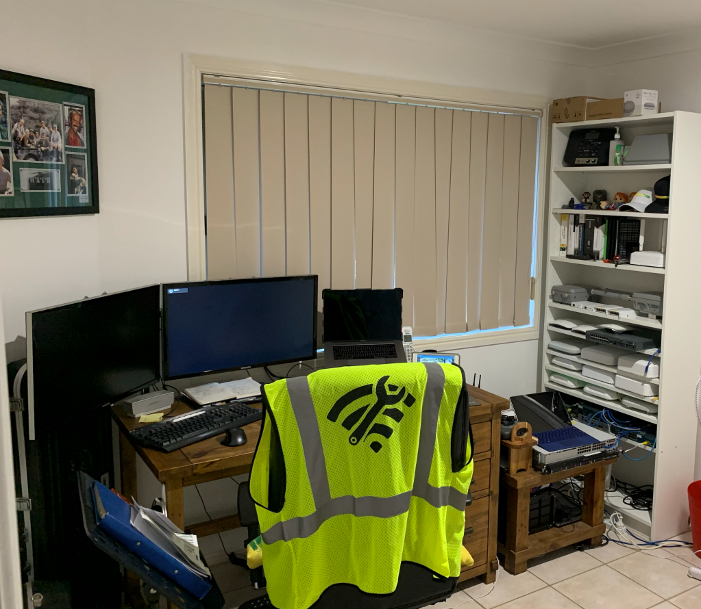
So after looking around and trying to come up with ideas, I decided to trial something different for the home office by using modular shelving rack system from a big brand hardware store. If it didn’t work out the shelves could be used in the my shed (no loss)

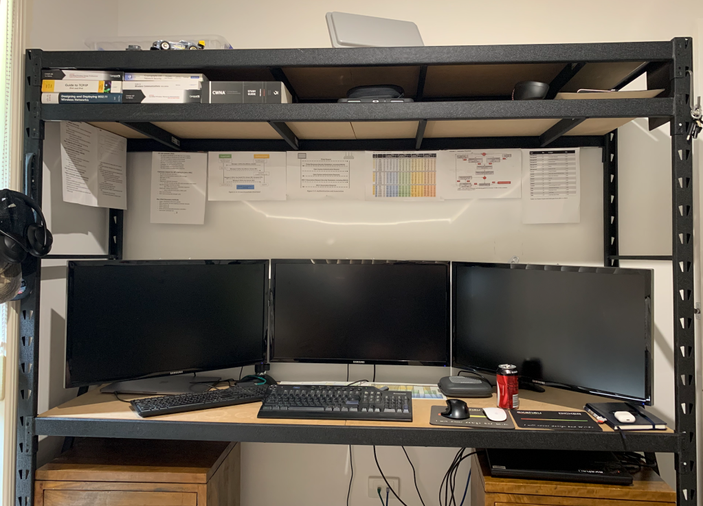
First I decided to get my office desk sorted, only adjustment was I had to raise the second shelf higher as I kept hitting my head on it when I stood up. I was extremely please with the end result. Plenty of space for 3x 28inch monitors, multiple keyboards and other bits and bobs and it is easy to keep tidy

New office desk setup

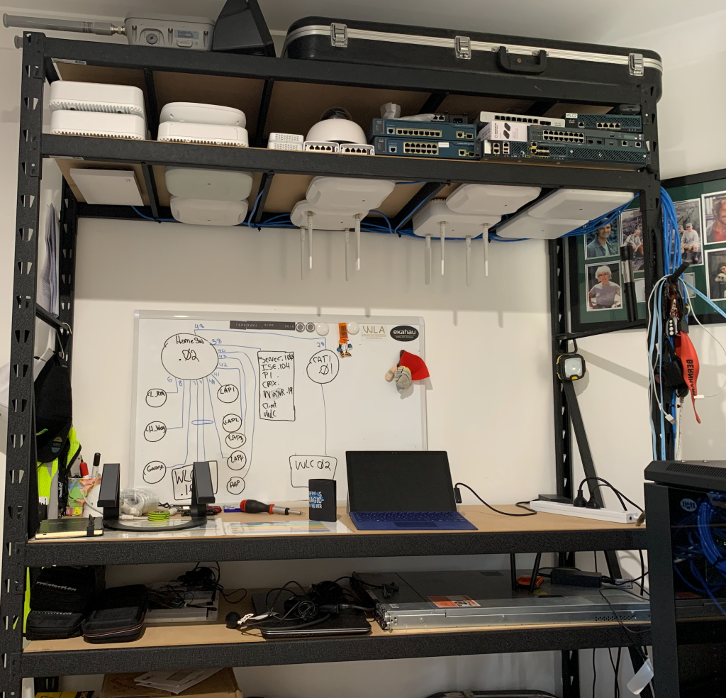
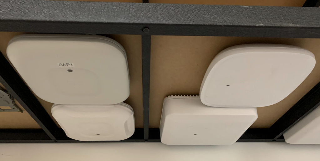
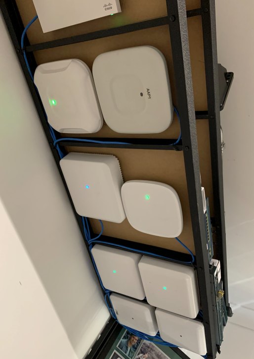
Happy with my office desk, next was to build my lab test area, I also moved the communication cabinet into my office as it needed to go from the garage. I decided to use the same modular rack system but this time higher and longer, and it turned out brilliant.
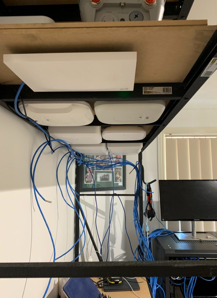
The End result.

Lab and work bench
Comms cabinet

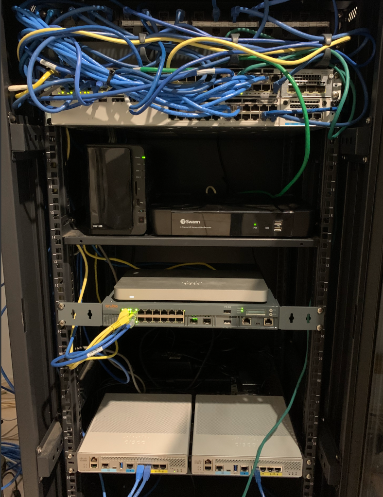
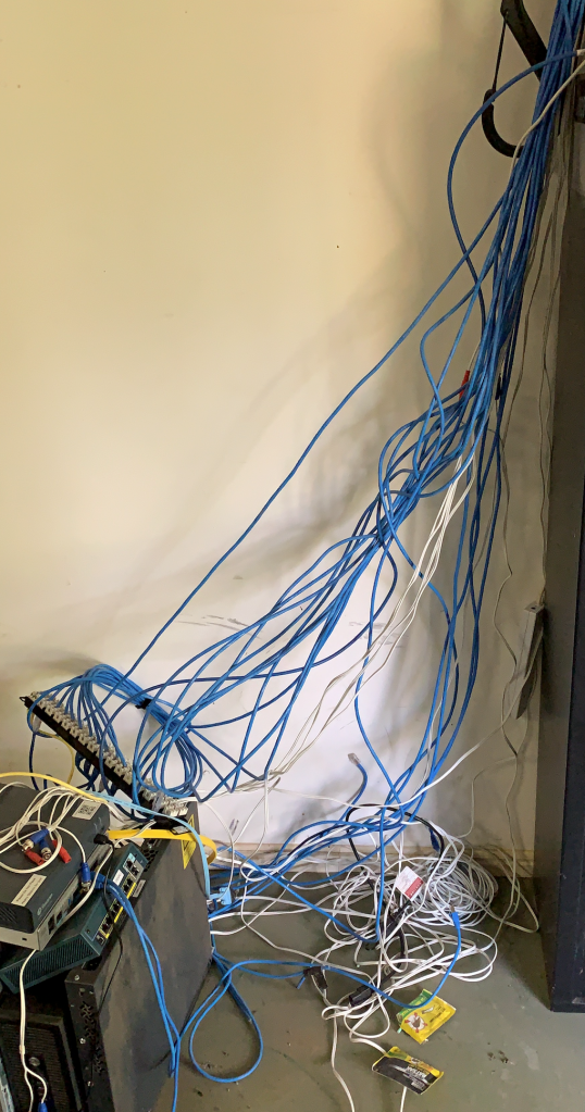
The hardest part of all this was the cable it just became a birds nest of cables and a nightmare in the roof.

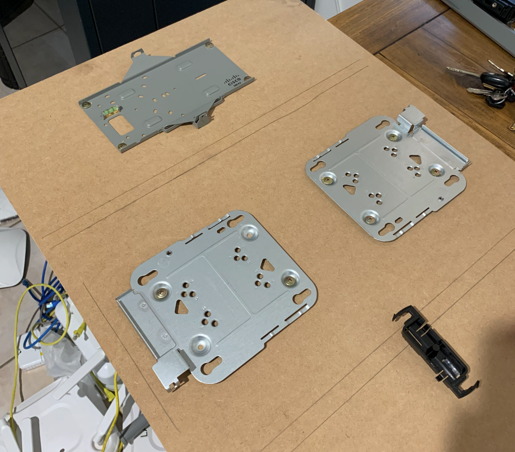
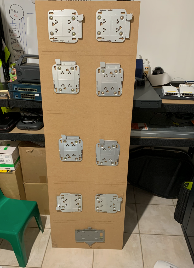
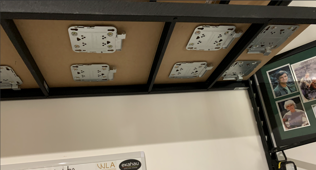
All the AP’s were mounted on a 1500mm W x 500mm D x 9mm H MDF with the AP mounts drilled in with 1/4 screws

AP mount installed
Installed to see if there was any space issues

Cisco and Cisco Meraki mounts drilled into MDF
Installed in Rack
APs installed
cutting cat6 to length
Terminating all Cat6 Cables
AP’s mounted in place

The equipment for the office desk is made by Rack IT , here is a list of the equipment you need as the amount of shelves is up to you, but I had 3 shelves for my desk,

2xUpright (legs) at 1830mm H x 530mm D, 2x “MDF shelf” per shelf at 900mm W x 500mm D x 9mm H” , 2x Beams per shelf 1800mm W x 50mm

The lab rack, I had 4 shelves for this so times everything by 4 expect the legs.

2x Upright (legs) 2135mm H x 530mm D legs, 1x “MDF shelf” 1500mm W x 500m D x 9mm H , 4 x ” shelf Support Brack” per shelf 500mm, & 2 Beams per shelf 1500mm W x 500H.

For the shelf that had the AP’s drilled into it I bought a another piece of MDF, to sit on top just in cast I drilled through, so it would not scratch anything that was place on that shelf.

Next post I will show what my outdoors wireless network looks like.

Metageek Wi-Spy AIR Review

I have been eyeing of the Wi-Spy-Air product for awhile and due to Covid-19 Metageek had an unbelievable 50% of sale, making purchasing the device an easy choice. So after using this device for the past few months I think it time to write up a small review about my thoughts on it.

Picture from Metageek site of the Wi-Spy Air

Some of the key selling points/features of this product is it’s small form factor, the ability to provide layer 1 & 2 information as well as information about connect clients. Easy to use simply plug it into your smart phone, click on the ” Airviewer” application that you have download from either App Store or Google play and away you go.

The Application Air View is easy to use and displays all relevant information clearly . love that get information about client devices and there roaming history.

Video of layer 1 spectrum view
playing around with. Wi-Spy Air menus

The device is small and easy to have it on you at all times to for those just incase moments.

comparing against of the devices that I use with similar features

The device comes with 4 rechargeable AAA batteries which can be recharge via the include USB mini cable.

As well as a heap of other different cable types to allow connection to other smart devices that you may have.

I currently have it setup so that it attaches to the back of my iPhone via velroc that is provided and so it does not block my camera, so I can still take photos if required, the setup seems to work nicely.

Pro’s

  • Small form factor
  • Excellent price and value $799US
  • Rechargeable AAA batteries
  • Integration with Chanalyzer version 5.12
  • Multiple cables for different connections types
  • Same spectrum sweep times as the Metageek DBx
    • 2.4 GHz 507 µsecs
    • 5 GHz 1587 µsecs
  • Can adjust scanning information and focus on specific channel ranges i.e U-NII-1 channels 36-48
  • Displays layer 1 and 2 information as has internal packet capture devices and spec an

Cons

  • Based on the Application versions at the time of this blog there are a couple couple of small glitches I experince
    • The App sometimes closes upon opening
    • Won’t detect Wi-Spy Air is connected at times, so have disconnect and reconnect.
  • Case could be built out of strong plastic as I feel it could be break or get damage rather easiliy.

Overall I am extremely happy with the product and has been my go to device for the past few months, where I would normally have had to pull out other devices that take more time to setup for the same result.

In conclusion I would recommend this product to the Wi-Fi Professional or hobbyist and if it was to get stolen or lost? I would buy it again.

Hope this was useful? leave a comment if there is anything else you would like to know otherwise, Cheers.

Wi-Fi Burns

Measure, measure and measure

There are many design consideration we need to account for in our RF designs. one of them is the impact objects such as:

  • Walls
  • Windows
  • Door
  •  other fixed structures

Have on signal propagation.

If we did not measure i.e a wall , how do we know what the loss is and what the affect that will have on our designs?  We don’t!

By performing attenuation measurements of structures, doors and walls etc, the data collected from this can then be use with a wireless design software  such as Ekahau or iBwave to simulated the RF,  so that we are able to better design a wireless network that meets the customers requirements

While there are times when we cannot measure and need to use a “estimated” dB loss values i.e.  building has not been built and need approximate for a  bill of materials

But if you a performing a wireless site survey regardless of the method you use with the intent of doing design, you must be doing attenuation measurements.

The skill set is not difficult to learn or hard to perform. Listed below are some resource that  have documented the theory, methodology and equipment need to perform this required task.

Tom Carpenter (2014) Certified Wireless Design Professional (CWDP-302 Edition). Cerititrek Publishing

https://www.ekahau.com/blog/2015/09/07/wi-fi-planning-walls-and-dbs-measuring-obstruction-losses-for-wlan-predictive-modelling/

Devin Akin (2018) Certified Wireless Design Professional Training course

Ekahau training course

Using Apple IOS devices to provide basic Wi-Fi information

The following information is a simple process that can be used to gather very basic Wi-Fi information from the perspective of the Apple IOS client device.

Information captured as part of the process can then be emailed and reviewed.

Required the following;

  • Apple IOS devices i.e. IPad
  • Airport Utility installed
  • Notes application  ( installed by default)
  • Email account synced to IPad

Step 1: Confirm Apple device has sufficient battery life for testing

Step 2:  If required  support contact details, as information collected can be emailed for review

Step 3: Understand how perform screen captures on your Apple device i.e. IPad “this may vary based on versions

1.PNG

The following steps will required access to the internet and apple app store to download “Airport Utility”.

Once the App has installed, the remainder of the steps for this section will be configuring and testing the application before using at in the field.

Step 5: Click on App store application

2.PNG

Step 6: In search bar type “Airport utility” and click on the app

3.PNG

Step 7: Click download button

4.PNG

Step 8: Upon completion of download, go to “Settings”

6.PNG

Step 9: In “Settings” scroll down to till you locate the “Airport Utility” application, click on it

7.PNG

Step 10: At the bottom click and enable “Wi-Fi Scanner”

10.PNG

  • Exit out of settings

Step 11: Click “Airport Utility” application

11.PNG

Step 12:  Click “Wi-Fi Scan”

12.PNG

Step 13: Click “Scan”

13.PNG

  • Wireless networks will hopefully start appearing. i.e.

Step 14: Click “Stop” after 15-30 seconds

14.PNG

Testing of application is now complete, exit out of application

Step 15: locate a fire evacuation map, they are usually located as you enter the area, take a photo on IPad

Step 16: Go to location of reported wireless issues,

Step 17: Click “Airport utility” application

11.PNG

Step 18: Click “Wi-Fi Scan”

12.PNG

Step 19: Adjust bar to 30 seconds

19.PNG

Step 20: Click “Scan”

19.PNG

  • (Wireless networks will hopefully start appearing). i.e.

21.PNG

    • The scan will complete upon reaching the duration it was set for i.e. 30 seconds

Step 21: Click22.PNG   located at the bottom of the screen

Step 22: Click “Copy”

24.PNG

Step 23: Exit out of application

Step 24: Click “Photos”

25.PNG

Step 25: Select the photo of map

Step 26: Click “Edit”

26.PNG

Step 27: Click 27.PNG located at top left of the screen

Step 28: Click “Markup”

28.PNG

Step 29: Select suitable color and marker

29.PNG

  • Identify and mark your location clearly
    • Be as accurate as possible

Step 30: Click “Done” twice

Step 31: Click 31.PNG

Step 31: Scroll across and click “More”

33.PNG

Step 32: Scroll down and click “Notes”

34.PNG

  • Photo will appear, click and pasted saved Wi-Fi Scan information

35.PNG

Step 33: Save “Note”

  • Repeat the process for all locations where wireless issues have been reported

The finale process if required is to send the capture information via emailed so that it can be reviewed

Step 34: Click “Notes” application

36.PNG

Step 35: Click on saved “note”

  • This will contained the photo and Wi-Fi Scan information i.e.

Step 36: Click


Step 37: Click “Mail” application”

39.PNG

  • This will automatically import all the saved information into the text field on the email.

40.PNG

    • Add information about the location name and details that may be relevant

Step 37: Send email to Wireless engineer to be reviewed


Reasons why not too install AP’s in false ceilings.

Its is bad design….

How can we design for something we cannot measure? A wireless design needs to account for signal attenuation, one of the big design requirements is to account for the loss caused by  walls, windows etc. We do this by measure the signal loss and accounting for it in our designs.

How would one  measure this the objects that are located in a false ceiling…? Well it would be extremely difficult to safely, accurately and not to mention costly to measure the HVAC  ducts etc located in false ceilings, especially when the  everything is already in place, as well how do you measure the impact of reflections etc???

Impact to coverage and efficiency of the WLAN….

In a typical corporate office multi level building the false ceilings can contain, HVAC ducting, water pipes, metal cable trays etc,  increasing reflections and sufficiently reducing signal propagation.

Reduced coverage  will result in extra AP’s having to be used to account for the coverage holes ,which result in an increase to overall cost.

Increased multi path caused by reflections can decrease overall throughput for less capable devices. Can cause AP radios to reduce power to account for the reflected signal being detected by the radio elements. Not good when design is based on RRM

Safety

AP’s can produce a great deal of heat (Cisco 4802) false ceilings are usually hot, contain dust and other material when combined can become a fire hazard.

Heat

As mentioned above AP’s and false ceilings can be rather hot, when AP’s are installed in false ceiling it is usually on some metal frame or structure, the increase heat can cause AP’s to overheat or fail.


Installing a Windows server CA signed certificate into ISE 2.4

Step 1: Download your Root CA certificate, depending on your setup this step may vary

  • In this example my certificate authority will be my home labs windows 2008 server, it is assumed that you have access to a CA server  or signed CA certificate already

Step 2: ISE use .pem format for its certificates, the Windows CA cert is a .cer format so we are required to changed the format, to do this I  will be using Openssl as I am using a Apple MAC which comes standard if using windows you will required to download the file.

  • In Terminal or what ever application you are using go to the location of where you have stored the certificate and enter the  following command

“openssl x509 -inform der -in cacert.cer -out isecacert.pem”

Step 3: Import the signed CA cert into ISE

  • Click on administration>system>certificates>trusted certificates
    • Click on Import

Screen Shot 2019-10-28 at 12.15.55 pm.png

  • Select the CA certification “isaca.pem”
    • Once  CA Certificate has been selected, clicked on the following 3 boxes to support EAP-TLS based authentication
    • Click submit

Screen Shot 2019-10-28 at 12.16.32 pm.png

Click submit.

Screen Shot 2019-10-28 at 12.17.02 pm.png

The Windows  server CA certificate will now appear in the Trusted Certificates list.

Using UC-232AC USB to serial adapter on a Apple Mac

The purpose of this blog post is to show the steps required on how to add the UC-232a USB to serial cable to your Apple MAC and then how to configure a profile so you don’t have to enter the commands again. I have had to do this a lot recently due to issues with my MAC so I thought I would document my own workflow on this process.

Step 1: Go  here and download the required drivers under Support & DownloadsYScreen Shot 2019-10-21 at 6.39.07 am.png

Step 2: Install the driver for the UC232a USB to serial cable it will require a reboot of your computer

Step 3: Open a terminal session, press command key and space then type “terminal” once located hit enter

Step 4: plug in UC-232AC USB to serial adapter into MAC

Step 5: In terminal program type:

$  ls /dev/cu.*

Located the /dev/cu.UC-232AC  as per below.Screen Shot 2019-10-21 at 6.40.12 am.png

Step 6: Type,

$  screen /dev/cu.UC-232AC 9600

Screen Shot 2019-10-21 at 6.43.04 am.png

And Now you should have CLU access to your device

Screen Shot 2019-10-21 at 6.46.58 am.png

If the below message is displayed in Terminal, dis-connect and reconnect  your USB to serial cable ;

Screen Shot 2019-10-21 at 6.47.20 am.png

Now to create a profile so you do not have to continually enter the commands

Step 6: Click on Terminal and select ” Preferences…”

Step 7: In the ” Profiles section” Click “+” icon located bottom left corner

Step 8: Type in your profile name i.e ” USB Serial”

Step 9 : In the shell tab that is part of your new profile you created, click “Run command” and enter in the text field: screen /dev/cu.UC-232AC 9600

Screen Shot 2019-10-21 at 6.54.06 am.png

Then close the window

Step 10: Right click on the terminal icon and go to ” New window with Profile” and select the profile you created

Screen Shot 2019-10-21 at 6.53.49 am.png

Now you should have CLI access to your device.

Screen Shot 2019-10-21 at 6.46.58 am.png

If the below message is displayed in Terminal disconnect and reconnect your usb to serial cable

Screen Shot 2019-10-21 at 6.47.20 am.png


That is it.

ECSE Design

I recently sat (Sept 2019) the Ekahau Certified Survey Engineer (ECSE) Design course in Melbourne Australia instructed by Eddie Forero the man behind badfi.com , course hosted by Dickerdata.com.au

The ECSE Design course is 1 of 3 courses that Ekahau offer, they also offer an Advanced and Troubleshoot course, for further information on  Ekahau and the courses refer here

The Design course covers the fundamentals of using the Ekahau software, RF, Design requirements and a heap more.

To ensure you get the most out of the course,  I would highly recommend you have a good foundational knowledge of wireless ( 802.11). One way of ensure this is by having read and grasped the material covered in the CWNA study guide book offered by CWNP, more information on this can found here: https://www.cwnp.com/certifications/cwna .

The first day of the course does cover what they refer to as CWNA lite,  but trust me and do yourself a favour, read and understand the material covered in the CWNA book before going on this course.

I had an absolute blast on this course,  Dicker Data (Darko) was a fantastic host & Eddie Forero a brilliant instructor.

Apart from the course another huge highlight was talking to different wireless professionals and the after training activities.  There was some great knowledge sharing conversation had!

Before doing this course I having been using Ekahau for many years, since transitioning from another product, but never completed any offical training, everything I learned came from experience (trial & error), CWNP, Ekahau guides, YouTube and advice from the twitter wireless community.

There is a wealth of information out there but it can certainly be overwhelming and steer you in the wrong direction.

I would highly recommend the ECSE Design course to anyone that wants to learn more about:

  • Wireless design requirements
  • Wireless capacity requirements
  • Wireless site surveys
  • Wireless documentation and reporting
  • Looking at doing the  ECSE-Advanced course as Design is a pre-req
  • Learning from experienced instructors that are veterans in this field.
  • And of course learn more about using Ekahau software and SideKick.

Big thanks to Darko from Dickerdata.com.au , Eddie badfi.com and of course Ekahau


Screen Shot 2019-09-15 at 1.09.39 pm.png

Basic overview of Wireless QoS

The purpose of this blog post is to hopefully provide a better understanding of wireless QoS without doing deep.

Wireless QoS simply put it is a method of prioritising certain types of frames, so that it spends less time waiting to transmit.

When talking about Wireless QoS most people are referring to either Wi-Fi Multimedia (WMM) or 802.11e.

WMM is a certification created by the Wi-Fi alliance to assist with the need for frame prioritisation while the 802.11e amendment was being signed off.  The 802.11e and WMM are somewhat similar in their structure.

Wireless QoS was defined in 802.11e amendment that is part of the 802.11-2016 standard, it was created to address particular requirements around latency and jitter for voice, video and audio traffic that is sent over the wireless medium, as the original 802.11 standard did not account for that type of traffic.

Two channel access methods are defined in the 802.11e amendment:

  1. Enhanced distributed channel access(EDCA) and
  2. Hybrid coordination function controlled channel access (HCCA)

Of the two, EDCA was adopted,

EDCA is used by both WMM and 802.11e capable clients. EDCA is a channel access method that allows certain types of traffic to be assigned to 4 queues called access category (AC).

The 4 AC are listed highest to lowest

  • Voice
  • Video
  • Best effort
  • Background

The AC are mapped to user priorities of which there is 8, within each AC there are two UP

  • UP 7 & 6 = Voice
  • UP 5 & 4 = Video
  • UP 3 & 0 = Best Effort
  • UP 2 & 1 = Background

The AC that a frame is placed in will determine how often it gets access to the wireless medium. I.e. a frame in the video queue will get more transmit opportunities than a frame in the Background queue.

Part of the 802.11 arbitration process is a wireless client must check that the medium is available before it transmit, this involves performing the following:

  • Carrier sense checks for further information on this refer to this post 
  • Inter-frame space (IFS)
    • A set period of time a STA cannot transmit a frame
    • For an 802.11e frame it is called arbitration inter-frame space (AIFS), basically the higher the AC the frame is placed into the short the AIFS timer will be
  • Random back off time
    • A random range of values called the Contention window (CW)
    • Each AC has minimum CW and maximum CW value. The higher the AC the lower the CW min and max value will be.

For a QoS frame, the IFS and the Random back off timer are extremely important, as it these timers that determine the period of time the client is waiting before it can send its frame. Less time waiting to transmit equals more transmit opportunities.

What has not be discussed is how this maps up to the wired side with layer 2 (COS) and layer 3 (DSCP) QoS markings, this will  be covered in another post.

References:

Westcott, David A.. CWAP Certified Wireless Analysis Professional Official Study Guide. Wiley. Kindle Edition.

Coleman, David D.. CWNA Certified Wireless Network Administrator Study Guide (p. 267). Wiley. Kindle Edition.


CCNP Wireless Deploy (300-365)

The following information is for anyone that is looking at or is currently studying for the CCNP Wireless Deploy (300-365) exam.

Information about the CCNP Wireless exams can be found here as well there is a CCNP Wireless study group

Study material is limited but I have listed what is available below, the best thing is to do given the limited official study material is breakdown the exam blue print and mark the sections of as you become confident in the topic.

Study material:

  • Cisco deployment guides based on the code version of the exam
  • Cisco CCNP wireless Quick reference guides

For this exam you will need to buy or borrow some lab equipment, so to ensure you grasp the topic’s in the blue print.

Equipment at a minimum:

  • 2x 2504
    • Can do most WLC configurations expect HA SSO and rate limiting
  • 4x 3502 or better
    • Can re-image 2 for Autonomous AP studies
  • Server that is able to run Prime, ISE, windows server, and windows client

This will enable you to do a lot of the topics in the blue print.

I sat the exam on March 2019, and passed on first attempt with about 20minutes of spare time left over.  Same with the CCNP-W Design exam the Deploy exam has the typical Cisco question, where it could have two right answer but the correct one depends on what document you read.

The exam does have configuration/troubleshooting questions as well as lab simulations in it, so hands on experience is a must if you aim to pass.